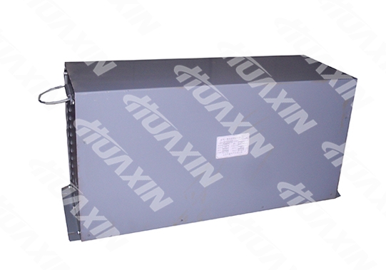
ZKT-2,156-550 Chopping Speed Regulator
1.The General Mining Chopping Speed Regulator is developed and manufactured to achieve energy saving and improve electronic control performance according to the status of speed regulation of the domestic electrical locomotive. It has the DC speed regulation system of closed-loop control. An Insulated Gate Bipolar Transistor (IGBT) is adopted in the system as the main power switching element, and the driving composition is controlled by the intelligent logic circuit. Compared with the ordinary resistance speed regulation system, it has the features of stable start, good speed regulation performance, less failure, strong protection function, and significant energy saving, etc.
2.The General Mining Chopping Speed Regulator consists of three parts, which are a General Mining ZKT-2×156/550 Chopping Speed Regulator, a QKT-2×156/550 General Chopping Controller and a Smoothing Wave Reactor. It can be used on a 20T Overhead Line Electric Locomotive to control forward, backward and parking of the locomotive. It achieves stepless regulation of the terminal voltage of the DC traction motor and controls its rotating speed.
3.Reference standards of the product:
MT/T1050-2007 Mine Electric Locomotive Driver Controller
GB/T12173-2008 General Electric Equipment for Mining
Q/HXDQ003-2011 QKT-2×156/550 Enterprise Standards of Mining General Chopping Controller

1. Rated Voltage: DC550V;
2 Rated Current: DC156A×2;
3 Maximum Current: DC300A×2;
4 Driving Motor Power: 78KW×2;
5 Operating Mode: Fixed Frequency Modulation;
6 Operating Frequency: 800Hz to 2K Hz;
7 Given Voltage Range: 0 to 4V;
8 Voltage Regulating Ratio a: 5%~95%;
9 Control Operating Voltage: DC24V1A;
10 Voltage Fluctuation Range: generally ±20% of the rated voltage (it can be set according to the users' requirements).
1. Energy Saving: compared with the Resistance Speed Regulating Electric Locomotive, its’ energy can be saved by over 30% at the speed regulation state.
2. Stable Start and High Starting Torque: by adopting the stepless speed regulation, a stable transition from start to full speed can be realized, and the mechanical system of the locomotive can be effectively protected. The locomotive speed can be controlled at discretion according to actual demands; and the tractive force is larger than that of the resistance speed regulating electric locomotive, so that the working efficiency is high.
3. Overcurrent Protection: When the locomotive is overloaded, the current protection circuit will work to make the motor current constant in order to ensure a safe operation of the motor.
4. Overvoltage and Under-voltage Protection: when the grid voltage exceeds or is lower than the voltage value set by the speed regulation device, the overvoltage and under-voltage protection circuit of the driving box will start working so as to protect the motor and speed regulation device from damage.
5. Non-arc Make-and-break: in normal operation, all contacts of the contact group have non-arc make-and-break, which greatly extends the service life of the contact.
6. Reliable Setting: photoelectric setting is adopted with good linearity and long life.
7. Block Structure: simple, compact and convenient for repair.
8. The closed structure is adopted for the speed governor, which has the dust proof and splash proof functions.
IGBT High-voltage High-power Switch is adopted for the speed regulation device, and a fixed frequency pulse-width modulation (PWM mode) control method is used. When the driving pulse is high level (+15V), the device will be connected. On the contrary, the device will be cut off at the low level (OV or -15V).
The IGBT is a series connected in the 'series excitation' traction motor circuit. When the IGBT is connected, the motor current will rise linearly; when IGBT is cut off, the motor current will form a circuit through the freewheel diode, and the current will decline linearly. Due to the high switching frequency, the actual motor current is equivalent to the direct current. By changing the proportion between the IGBG connection and disconnection time (i.e., voltage regulating ratio a=TON/T or Uout/ Uin), the voltage average value of the motor can be changed, so as to change the motor speed, and meet the purpose of locomotive speed regulation. When the IGBT works at the switch on/off state, the loss is very small at connection and disconnection. Therefore, the energy saving effects are significant at the speed regulation state. Various protection functions of the speed regulation device (soft start, under-voltage, overvoltage, overcurrent,etc.) can also be met through the proportion of IGBT connection and disconnection.
1. The elevation shall not exceed 1,200m.
2. The ambient temperature should between -25℃ and 40℃(-13℉ and 104℉), and the annual average temperature should not not exceed +25℃/77℉.
3. The monthly average maximum relative humidity of the wettest month shall not be more than 90%.
4. Inclination from the normal position shall not be more than 10°.
5. It has sinusoidal vibration with frequency f as (2 to 50)Hz in the vertical, horizontal and longitudinal directions of the locomotive, and the vibration amplitude should not larger than A, A is:
A=25/f mm, when 2Hz≤f≤10Hz
A=250/f2 mm, when 10 Hz<f≤50Hz
6. Maximum Impact Acceleration:
———Longitudinal Direction (vehicle travel direction) 30m/s2
———Horizontal Direction 20m/s2
———Vertical Direction 10 m/s2
7. Places without excessive conductive dust or harmful gas in the air, and without explosion hazard.
8. It should be installed in the rain-proof, snow-proof, splash-proof and dust-proof facilities.
Contact information
-
About Huaxin
-
Follow Us


-
Share Us
©1996-2023 晉ICP備07500050號 Huaxin Copyright
©1996-2023 晉ICP備07500050號 Huaxin Copyright


